High-speed switch/actuator
ANSYS FEA was used to analyzed a complex switch/actuator assembly. This helped us understand the stresses during a sudden stop caused by an impact with the steel hard stop. See Figure 1.
We compared this setup to one with a shock-absorbing stop, shown in Figure 6. If we can reduce the impact effects, we can use a less costly material. Shortly after completing this analysis, the testing began on the prototype assembly, and the predicted deformation in the hard stop proved correct.

Figure 1 – CAD model

Figure 2 – CAD model mechanism detail. Plates not shown for clarity.
This model was simplified to its essential elements and subjected to a dynamic finite element analysis using the transient structural solver.

Figure 3 – Close up of hard stop.
Cad model shown in open position, springs compressed. Mesh controls were used extensively in order to concentrate the finer mesh near the areas where high stress occurs to help keep run times down. We continuously used this process during model development.
.
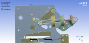
Figure 4 open position. Springs compressed

Figure 5 closed position. Springs extended
The switch design requires actuation time in milliseconds. The high-impact energy on the steel stop applies enough force to deform the part.
Shock –Absorbing Stop
I changed the stop to one with a shock-absorbing feature, shown in Figure 3. It underwent the same analysis method as the hard stop. See Figure 6.

Figure 6 – FEA soft stop model. Note springs between plates that represent energy- absorbing material

Figure 7 – Soft stop shown as steel plates separated by analytical springs, simulating energy-absorbing material.
Solid Stop Impact Stresses
The following figures provide detail of the stress levels resulting from use of the solid steel stop.
Shock absorber model (Soft Stop)
To see how shock absorbers affect hard stops, we added a simple soft stop model to the actuator model. Figure 23 shows this.
The model has steel plates spaced apart. It also includes analytical springs at six equal points in between. Each spring has a constant of 12,000 lbs./inch.
The impact stress effects are significant, as seen in the figures below. All figure legends are the same.
The highest stress around the stops drops from 230,000 psi to 101,000 psi. To justify using carbon steel, dynamic stress should remain below 90,000 psi.
value depends on the chosen grade of steel.

Figure 9 – Impact area showing hard stop model stresses. max stress 230,000 psi
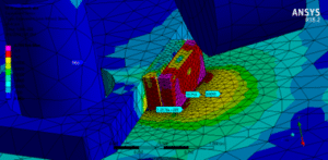
Figure 10 – Impact area showing effects of shock absorber model. max stress 103,000 psi
Soft Stop Design
The soft stop shown is not intended as a design suggestion but to demonstrate the effect that such an assembly could have on the forces generated during impact. One design that comes to mind is the rotational stop used on the Hercules – basically 2 steel plates with an elastomer in between.
Conclusions
The effects of a solid actuator stop on the actuator components would generate stresses that would bend and/or break them, even if they were made from 4140 steel, with a yield stress of 986 Mpa (142,000 psi).
Testing shortly after this analysis was published confirmed my analysis.
A properly designed soft stop may be able to reduce the impact stresses to a level where a less costly material could be used.